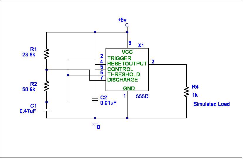
This is the timing circuit that will be used to provide a clock to the control circuit. Our design required that the clock frequency be at 24 Hz. I purchased an NTE955M from a local electronics store and downloaded the data sheet from the manufacturer’s web site. According to the manufacturer’s literature, the output frequency could be determined by selecting the correct values for R1, R2, and C1.
The formulas for determination of the output frequency, from the data sheet are:
The period is: T = 1 / f 0 (where f 0 is the frequency desired.)
Charge time (output high): TH = ln(2) * (R1 + R2) * C1
Charge time (output low): TL = ln(2) * R2 * C1
Total period is: T = TH + TL
The output frequency: f 0 = 1 / T = 1 / (ln(2) * (R1 + (2 * R2)) * C1)
The duty cycle: D = R2 / (R1 + (2 * R2))
I found through some quick calculations that a duty cycle value of 50% leads to R1 equal to zero. By adjusting the duty cycle above 50% in value, a good value for R1 could be determined. I settled on a duty cycle value of 60%. Here are the results of my calculations. (Since I had on hand a capacitor whose value was 0.47
mF, this was my C1 value.)mF) = 51,159 W.f 0 = 24 Hz therefore T = 1 / f 0 = 41.66 ms
R2 = TL / (ln(2) * C1) = 16.6 ms / ( 0.693 ms * 0.47
R1 = TH / (ln(2) * C1) – R2 = 25 ms / ( 0.693 ms * 0.47
mF) – 51,159 W = 25,580 W.The closest available values for R1 and R2 are: R1 = 24 k
W and R2 = 52 kW.The measured values were: R1 = 23.6 k
W and R2 = 50.6 kW.The calculated output frequency is: f 0 = 1 / ( 0.693 ms * 124.8 k
W * 0.47 mF) = 24.6 HzThe measured output frequency was: f 0 = 24.59 Hz.
If you have questions or comments, please email me at: