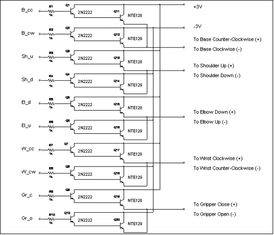
Transistor Control Circuit for the Robot Project

This is the transistor circuit that will be used to control the motors of the robotic arm. This circuit is the interface between the control logic and the robot itself. I decided to use a Darlington configuration of the transistors so I could have enough current through the motors of the robotic arm. When I measured the activation current of the robotís motors, I found that the value for the current was between 340 and 380 milliamps. By researching an NTE manual, I was able to select two transistors for switching and current capability. The NTE128 and NTE129 complement pair can each handle a maximum of 1 amp through their collectors so I chose these common transistors as the robot motor drivers (plus it kept the cost of the circuit down). I chose the NTE123 as the transistor that turns on and off these driver transistors because it is commonly used as a switch and is readily available. I tested the transistor configuration on each robot motor and each motor worked as expected.
The inputs to the control circuit are on the left side of the diagram. These will be connected to the outputs of the logic control circuit. Each of these inputs is activated by a 5 volt pulse from the logic control circuit. While the input is at 5 volts, the specified motor will activate. When the 5 volts drops to 0 volts, the motor stops. The outputs of the control circuit are on the right side of the diagram. These will be connected to the robot itself via a ribbon cable. Once the connections are established, the robotic arm will be completely controlled from the logic control circuit.
If you have questions or comments, please email me at: